GalMakes
Evil Cat
Fun project where I build a laser-powered, motion-detecting guard cat to keep my real cat in check. Using sensors, lights, and a touch of humor, this DIY companion is part security system, part feline rival.
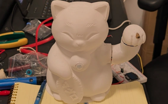
Evil Cat - The mighty protector
It all started when our son joined the family—and our sleep schedule vanished. We quickly had to adapt to a new routine: catching sleep in short bursts between his feeding and nap times. In those precious windows of rest, every minute mattered.
But our cat, Zohar, had other plans.
She was used to hopping onto our bed every night for her pre-sleep dose of attention. Suddenly, we weren’t available—and she wasn’t happy about it. Whenever we tried to go to bed without giving her the usual affection, she would storm into the room, meow loudly, and pounce on us. That’s when I realized: if we ever wanted to sleep again, I needed to find a way to keep her entertained, and out of our bedroom.
Design
I started brainstorming ideas that could keep Zohar busy and engaged—something automatic, consistent, and located just outside our room.
At first, I prototyped using an ESP32-C3, but its built-in antenna didn’t provide the stable connection I needed. I then upgraded to the ESP32-WROOM module. It’s a bit larger, but its improved antenna performance made a huge difference in connectivity.
For inspiration, I thought: what’s more amusing to a cat than another cat? That led me to design a 3D-printed Maneki-neko (the Japanese “lucky cat”) in Blender—and I named it the Evil Cat.
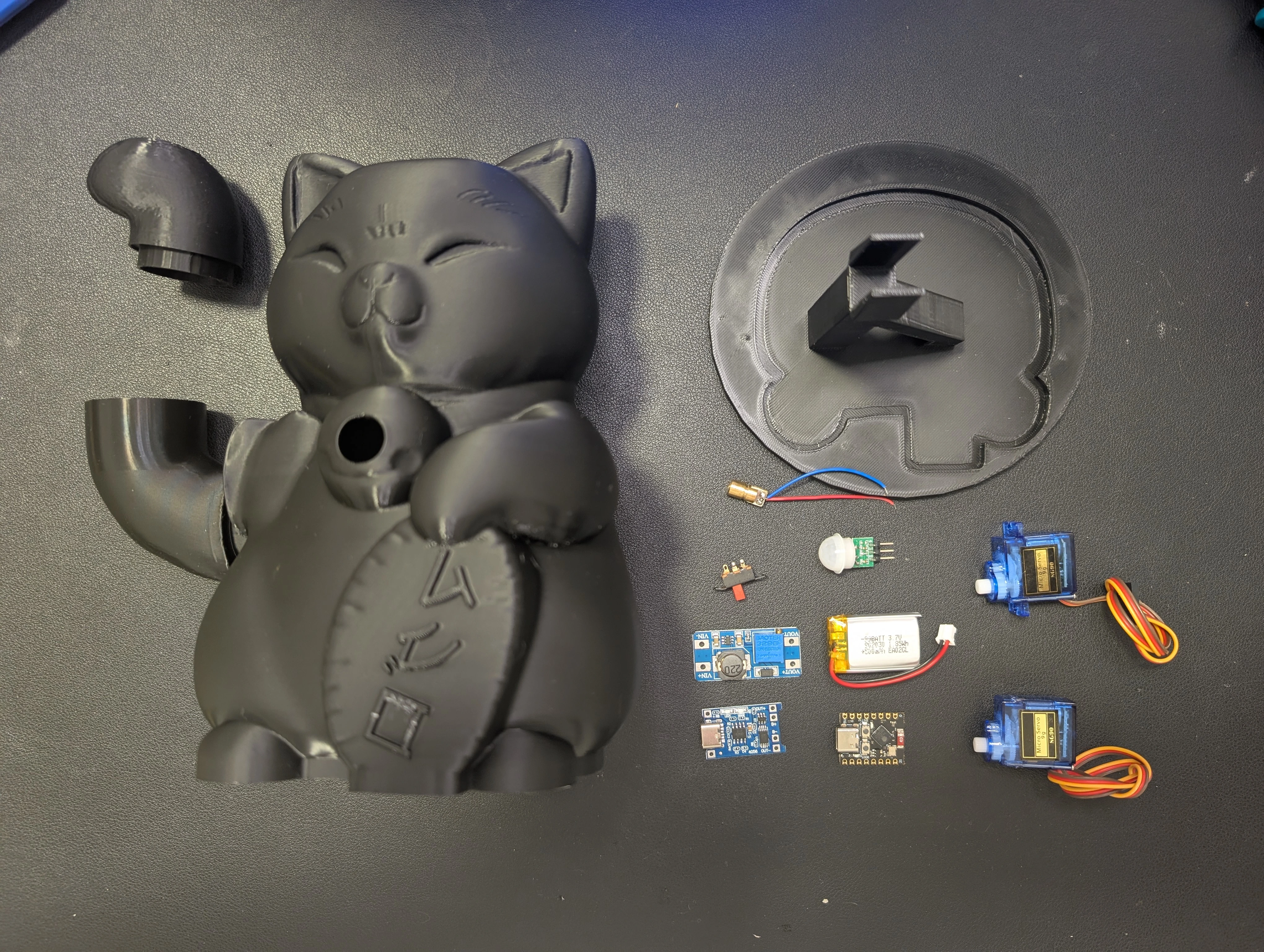
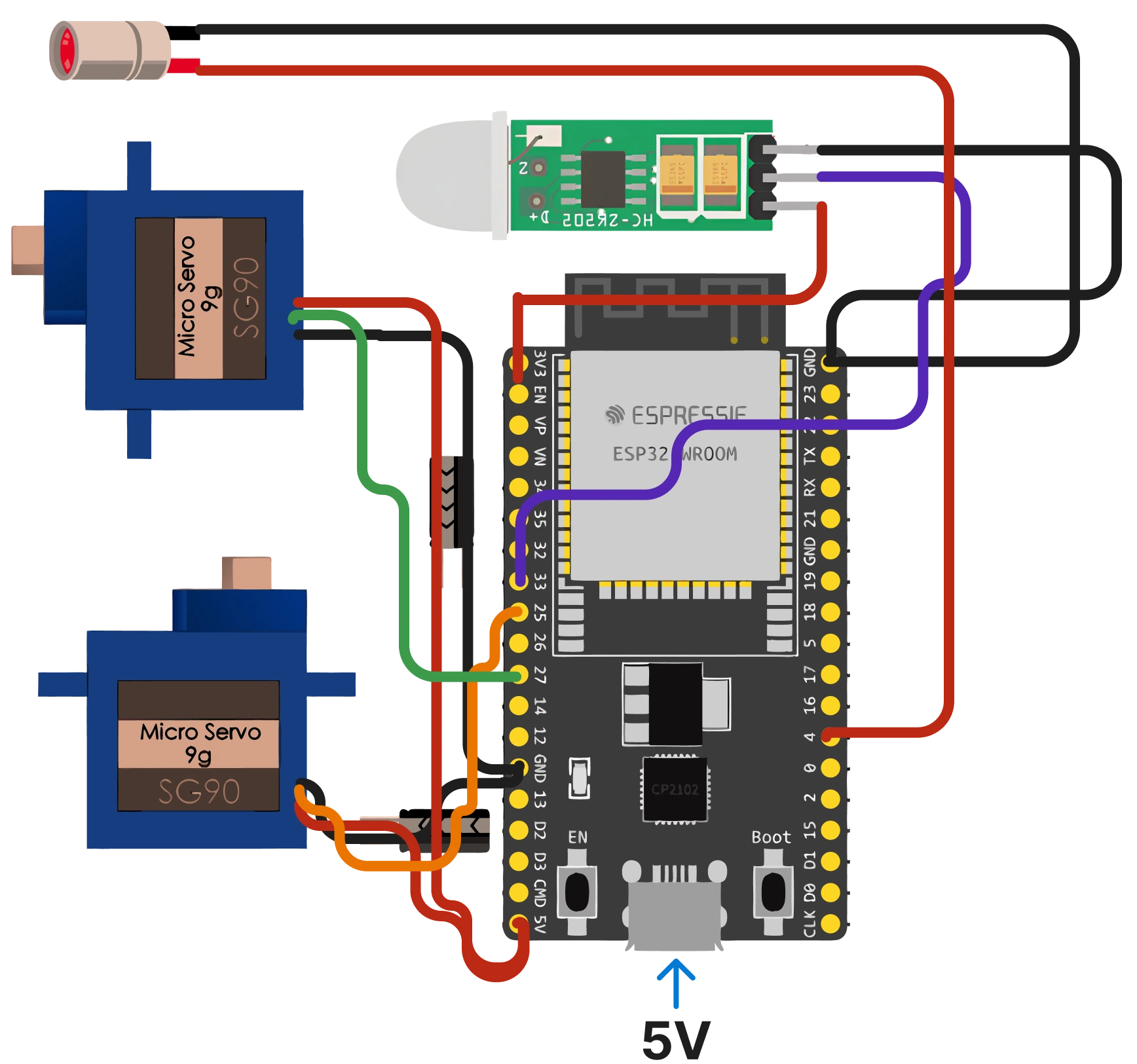
The concept was simple: Evil Cat would sit just outside our bedroom door. It would use a mini PIR motion sensor (HC-SR312 / AM312) to detect movement. When Zohar approached, Evil Cat would come to life—waving its paw with an SG90 servo motor and activating a laser pointer. The laser would dance on the floor, grabbing Zohar’s attention and luring her away from our door.
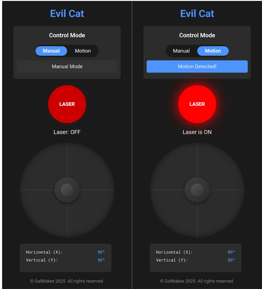
For extra fun, I also wanted to control Evil Cat remotely. So I planned to build a simple web interface that I could open from my phone, allowing me to manually activate the laser and move it around using servo controls—just in case I wanted to give Zohar a little extra playtime on demand.
Once the motion stopped and Zohar lost interest, Evil Cat would power down—silent and still—until it was needed again.
Electronic diagram maker
Project Steps: Build Your own Evil cat
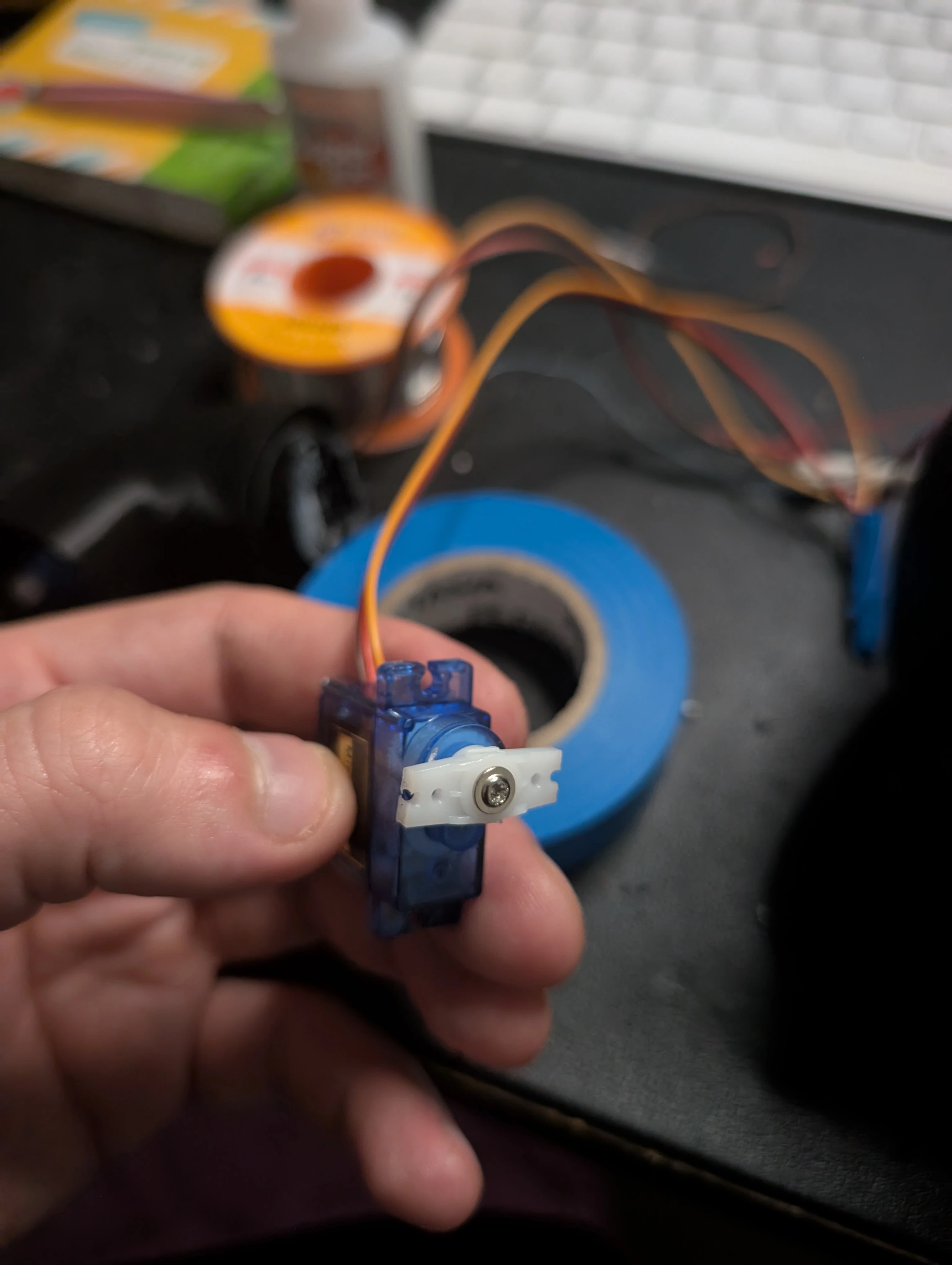
1. Modules testing
Before creating the Evil Cat body in 3D modeling, I needed to verify that all components were working properly. I used a breadboard to temporarily assemble the parts with code that included all functionality. When I moved my hand over the PIR sensor, the laser turned on and the servo began moving as expected. In this phase I learnd that the servo motor take power in a way that I didn't expect, and cause the servo to have power spikes. To solve this I added a capacitor to each servo to smooth the power supply.
2. 3D Model and printing
I started by gathering inspiration online and identified three websites I recommend, each providing a variety of modules you can print or customize to create your own designs.
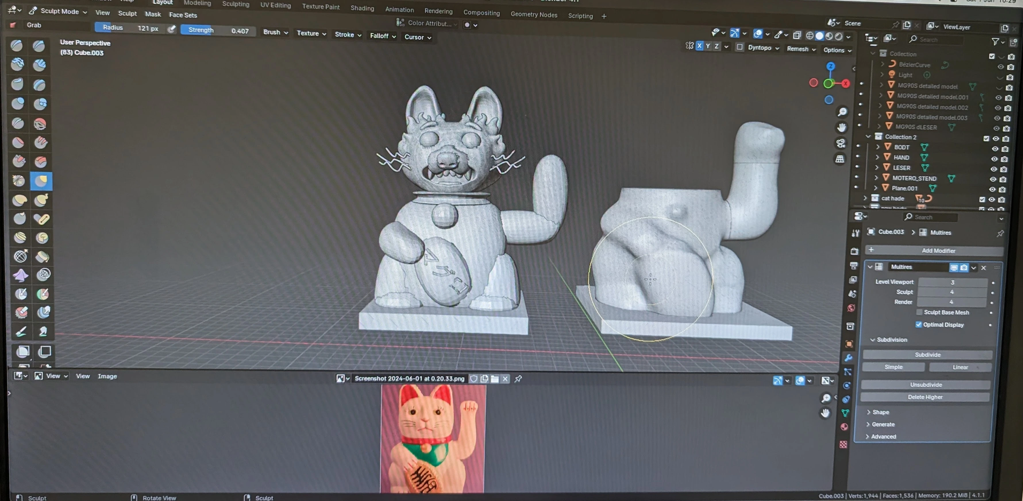
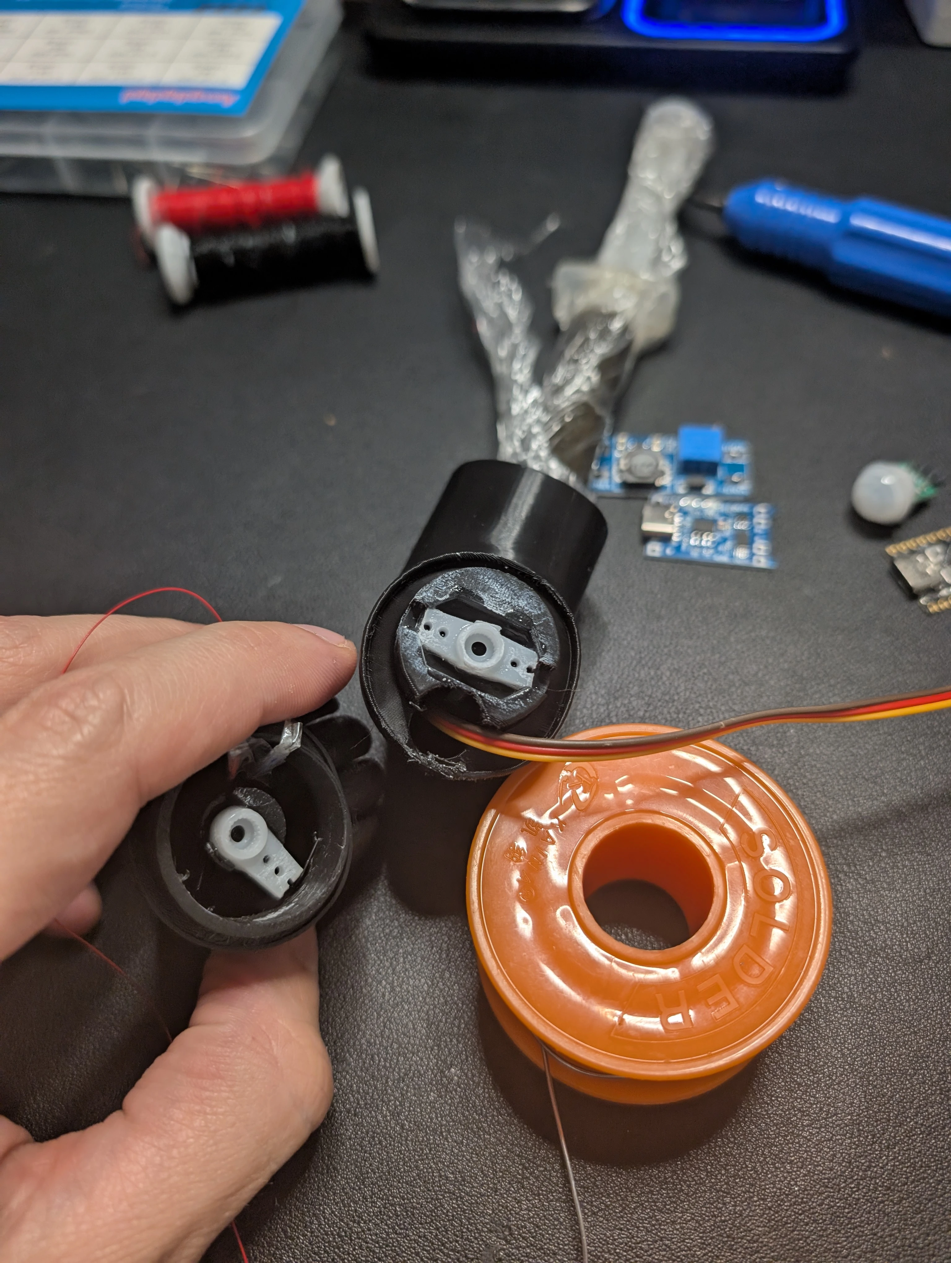
For creating non-geometric 3D prints, I prefer using Blender over Fusion 360 due to its excellent artistic tools, such as sculpting, which enhance module texture and detail. I initially attempted to design my own Evil Cat from scratch, but the process became overly complex. To simplify the structural design, I opted to use available web modules and then focused on refining the details. I measured the dimensions of the various modules to be integrated into the Evil Cat body and developed a prototype to house all components. This approach helped verify that the sizes, connections between moving parts, and motor capacity to support the arm's weight were all functioning correctly. This was the first time I used Blender and I was impressed by the quality of the 3D models and the ease of use. Here is my prototype model:
3. Assembly
Now that Evil Cat’s body was ready, I began assembling all the components—soldering the electronics and finishing the physical build so I could finally move on to writing the code that would bring it to life.
To connect the servo motors to the cat’s arm and body, I initially tried to avoid using glue, but the rapid movements of the servo created small shock waves that eventually caused the arm to detach. In the end, I used superglue to secure the servo horn to the 3D-printed arm, ensuring a firm hold. To support the entire arm mechanism, I also designed and printed a custom stand that keeps the main servo motor stable during operation.
4. Board test – Make Sure the ESP32 Works
lets start with making sure your board have proper WIFI anatnt and it can acsses your wifi, for that we will need a short C++ and HTML code. We will start with adding the libararys we need for the project <WiFi.h>, <ESPAsyncWebServer.h> and <AsyncTCP.h>
Library Descriptions
- <WiFi.h>: This library enables the ESP32 to connect to a WiFi network, providing the foundation for internet connectivity. I chose it because it’s essential for setting up a web server that can be accessed remotely, allowing seamless communication between the ESP32 and client devices.
- <ESPAsyncWebServer.h>: This library facilitates the creation of an asynchronous web server on the ESP32, handling HTTP requests efficiently without blocking other tasks. I selected it for its non-blocking nature, which ensures smooth operation and responsiveness, especially when toggling the LED via web commands.
- <AsyncTCP.h>: This library supports asynchronous TCP communication, which is a dependency for ESPAsyncWebServer.h. I included it to ensure reliable and efficient data transfer between the ESP32 and connected clients, complementing the web server’s performance.
Open your IDE if its Curser/VScode Arduino or any other that compitable with Arduino coding and add the follwing code
here is an example code
// Basic Web Server for ESP32
#include <Arduino.h>
#include <WiFi.h>
#include <ESPAsyncWebServer.h>
#include <AsyncTCP.h>

// WiFi credentials for ESP32 connection
const char* ssid = "<Your SSID>";
const char* password = "<Your Password>";

// LED pin
const int ledPin = 2; // GPIO 2, change this to your LED pin
bool ledState = false;

// Create AsyncWebServer object on port 80
AsyncWebServer server(80);

// HTML content with button to toggle LED
const char* htmlPage = R"rawliteral(
<!DOCTYPE html>
<html>
<head>
  <title>ESP32 Web Server</title>
  <meta name="viewport" content="width=device-width, initial-scale=1">
  <style>
    body { font-family: Arial, sans-serif; text-align: center; margin-top: 50px; }
    button { padding: 10px 20px; font-size: 16px; cursor: pointer; }
  </style>
</head>
<body>
  <h1>Hello Test</h1>
  <p>LED State: <span id="ledState">%STATE%</span></p>
  <button onclick="toggleLED()">Toggle LED</button>

  <script>
    function toggleLED() {
      var xhttp = new XMLHttpRequest();
      xhttp.open("GET", "/toggle", true);
      xhttp.send();
    }

    function updateLEDState(state) {
      document.getElementById("ledState").innerText = state;
    }

    // Initial state update
    setInterval(function() {
      var xhttp = new XMLHttpRequest();
      xhttp.onreadystatechange = function() {
        if (this.readyState == 4 && this.status == 200) {
          updateLEDState(this.responseText);
        }
      };
      xhttp.open("GET", "/state", true);
      xhttp.send();
    }, 1000);
  </script>
</body>
</html>
)rawliteral";

String processor(const String& var) {
  if (var == "STATE") {
    return ledState ? "ON" : "OFF";
  }
  return String();
}

void setup() {
  // Initialize LED pin as output
  pinMode(ledPin, OUTPUT);
  digitalWrite(ledPin, LOW);

  // Start serial communication
  Serial.begin(115200);

  // Connect to WiFi
  WiFi.begin(ssid, password);
  while (WiFi.status() != WL_CONNECTED) {
    delay(1000);
    Serial.println("Connecting to WiFi...");
  }
  Serial.println("Connected to WiFi");
  Serial.println(WiFi.localIP());

  // Serve the HTML page
  server.on("/", HTTP_GET, [](AsyncWebServerRequest *request){
    request->send(200, "text/html", htmlPage, processor);
  });

  // Handle LED toggle request
  server.on("/toggle", HTTP_GET, [](AsyncWebServerRequest *request){
    ledState = !ledState;
    digitalWrite(ledPin, ledState);
    request->send(200, "text/plain", ledState ? "ON" : "OFF");
  });

  // Handle LED state request
  server.on("/state", HTTP_GET, [](AsyncWebServerRequest *request){
    request->send(200, "text/plain", ledState ? "ON" : "OFF");
  });

  // Start server
  server.begin();
  Serial.println("");
  Serial.println("Connected to WiFi!");
  Serial.print("IP address: ");
  Serial.println(WiFi.localIP());
}

void loop() {
  // Nothing to do here, handled by AsyncWebServer
}
In my network setup, I use a router and firewall, which required proper configuration to allow the ESP32 to connect to the network and host a web server locally. If you run the code below and encounter a 404 error, it might be due to network configuration issues. To verify if this is the case, open your terminal and ping the IP address displayed in the ESP32 Serial Monitor. If you receive a ping response, the server is likely running, but your network settings may be blocking access.
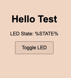
if all work you should get this view:
5. Code
I’ll walk you through the main parts of the code—though the full project is available in the GitHub repository.
Let’s focus on the script section that interacts with the ESP32 through API calls. (The full HTML layout is omitted here for brevity.) Below, you’ll find explanations of the core JavaScript methods I used and the coding fundamentals behind them.
HTML + JavaScript Web Interface (MAIN_page)
This section defines the HTML page served by the ESP32 to the user's browser. It's stored in flash memory using the PROGMEM keyword and a raw string literal (R"rawliteral(...)")
const char MAIN_page[] PROGMEM = R"rawliteral(
<!DOCTYPE html>
<html lang="en">
    <script>
    ...
    </script>
</html>
)rawliteral";
document.getElementById()
The document.getElementById() method is used to select DOM elements from the webpage by their id attributes, retrieve elements with the ID and motionIndicator. It enables JavaScript to reference specific HTML elements, allowing you to read or modify their content, styles, or behavior dynamically. At its core, this is a fundamental concept of DOM (Document Object Model) manipulation, which forms the basis for interacting with and updating web pages in real-time.
const modeToggle = document.getElementById('modeToggle');
const motionIndicator = document.getElementById('motionIndicator');
Event Listener Pattern
Attaches an event listener to the modeToggle button, triggering the specified function whenever the user clicks it. This setup is used to handle user interactions asynchronously, allowing the program to respond dynamically to actions like clicks without blocking other processes.
modeToggle.addEventListener('click', function() {
    ...
});
fetch() API – HTTP Requests from JavaScript
The fetch() API is used to send HTTP requests to the ESP32 server, allowing JavaScript to interact with the web server and retrieve data or send commands. This is a fundamental part of the web communication protocol, enabling real-time data exchange between the client (browser) and the server (ESP32).
fetch('/api/mode?manual=' + (isManualMode ? 1 : 0))
    .then(response => response.text())
    .then(data => {
        console.log('Mode change response:', data);
Chained Promises (.then() and .catch())
.then() executes when the request succeeds, processing the response text, while the .catch() triggers if an error occurs, such as a lack of Wi-Fi connectivity. This approach is used because Promises ensure the code progresses only after the request completes, providing a structured way to manage asynchronous operations. This reflects the fundamental concept of asynchronous programming with Promises, enhancing the reliability of web-based interactions.
fetch('/api/mode?...')
  .then(response => response.text())
  .then(data => console.log('Mode change response:', data))
  .catch(error => console.error('Error changing mode:', error));
JSON Response Handling
The .then(response => response.json()) line in the code parses the HTTP response as JSON, enabling JavaScript to access specific fields such as data.detected from the response data. This is used because JSON serves as a lightweight and widely adopted format for exchanging data between the server and client, simplifying communication.
.then(response => response.json())
Server-Side Code (server.cpp) - API Endpoints
The API calls sent from the web interface ultimately trigger specific functions on the microcontroller. Let’s go over the four different APIs used in this project.
    server.on("/api/servos", HTTP_GET, handleServoControl);
    server.on("/api/laser", HTTP_GET, handleLaserControl);
    server.on("/api/mode", HTTP_GET, handleModeChange);
    server.on("/api/motion", HTTP_GET, handleMotionStatus);
handleModeChange:
Switches between manual and motion-detection mode by toggling the autoMode flag. Responds with the current mode.**
void handleModeChange(AsyncWebServerRequest *request) {
  autoMode = !autoMode;
  request->send(200, "text/plain", autoMode ? "Auto" : "Manual");
}
handleMotionStatus:
Returns the current state of the PIR motion sensor.
void handleMotionStatus(AsyncWebServerRequest *request) {
 int status = digitalRead(PIR_PIN);
 request->send(200, "text/plain", status ? "Motion" : "No Motion");
}
handleServoControl:
Parses 'a' and 'b' query parameters from the request and sends new target positions to the servos.
void handleServoControl(AsyncWebServerRequest *request) {
if (request->hasParam("a") && request->hasParam("b")) {
  int a = request->getParam("a")->value().toInt();
  int b = request->getParam("b")->value().toInt();
  moveServos(a, b);
  request->send(200, "text/plain", "OK");
} else {
  request->send(400, "text/plain", "Missing params");
}
}
handleLaserControl:
Sets the laserOverride flag based on the state query param ("on" or "off") to manually toggle the laser.
void handleLaserControl(AsyncWebServerRequest *request) {
  if (request->hasParam("state")) {
    String state = request->getParam("state")->value();
    laserOverride = (state == "on");
    request->send(200, "text/plain", laserOverride ? "Laser On" : "Laser Off");
  } else {
    request->send(400, "text/plain", "Missing state param");
  }
}
loop() Function
This is the main control loop:
- In auto mode, the PIR sensor watches for sustained motion.
- If motion is detected for more than 2 seconds, the laser turns on.
- The servos then trace a circular path using sine and cosine, simulating a playful laser movement.
- After 5 loops or if auto mode is disabled mid-sequence, the routine stops.
- The servos then return to center using
smoothMoveToCenter().
- In manual mode, the laser is simply controlled via the
laserOverrideflag from the web interface.
void loop() {
  if (autoMode) {
    if (digitalRead(PIR_PIN) == HIGH) {
      if (!motionDetected) {
        motionStartTime = millis();
        motionDetected = true;
      }
      if (millis() - motionStartTime > 2000) {
        digitalWrite(LASER_PIN, HIGH);
        for (int i = 0; i < 5 && autoMode; i++) {
          for (int angle = 0; angle < 360 && autoMode; angle += 10) {
            float rad = radians(angle);
            int x = 90 + 30 * cos(rad);
            int y = 90 + 30 * sin(rad);
            moveServos(x, y);
            delay(50);
          }
        }
        digitalWrite(LASER_PIN, LOW);
        smoothMoveToCenter();
        motionDetected = false;
      }
    } else {
      motionDetected = false;
    }
  } else {
    digitalWrite(LASER_PIN, laserOverride);
  }
}
The challanging part was to calculate the circle path for the servos, I used sin and cos to calculate the x and y coordinates of the servos, here is the explanation:
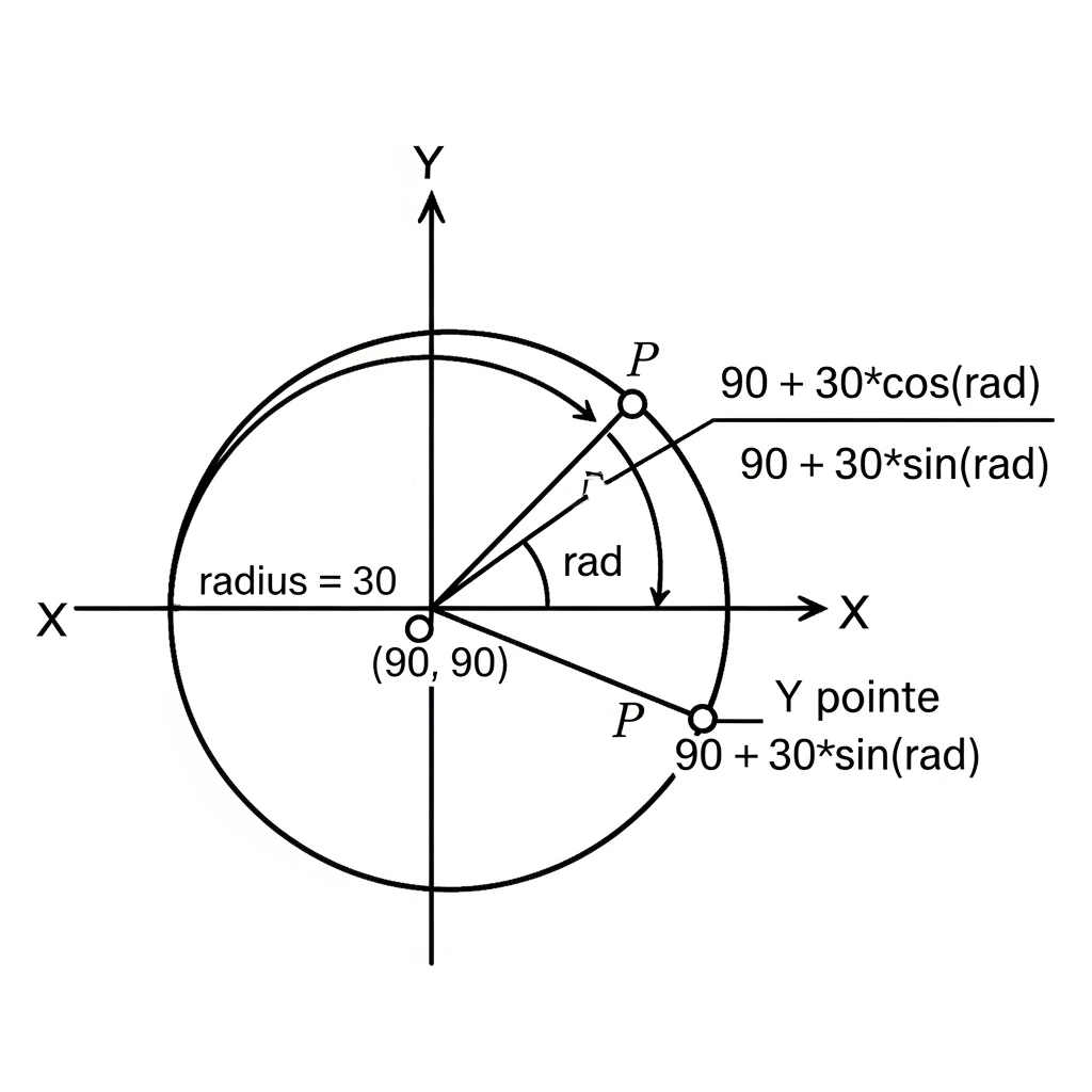
- The Center: The circle's center is shifted from the origin (0,0) to the point (90,90).
- The Radius: The 30 * cos(rad) and 30 * sin(rad) parts determine the X and Y displacements from this center point. The 30 is the radius of the circle.
- The Angle (rad): As the angle (and thus rad) changes from 0 to 360 degrees (0 to 2π radians) in the for loop: cos(rad) and sin(rad) cycle through their values. This makes the point P(x,y) trace a path around the center (90,90) at a constant distance of 30 units, forming a circle. The code calculates these (x,y) points for various angles (0, 10, 20, ... 350 degrees) and moves the laser to each point, drawing the circle step by step.
Materials
- ESP32 Development Board$1.94
- Servo Motor$2.87
- Laser 3V$2.00
- PIR Motion Sensor$1.30
- Total Cost$8.11
Required Tools
- Soldering Iron
- Wire Strippers
- 3D Printer
- MultimeterOptional
- Hot Glue GunOptional